(509)421-2767
5653 Campbell Rd
Peshastin, Chelan County 98847
USA
CONTACT ME
If you have any questions or concerns, please contact me to learn more.

Construcion
Analysis
In order to support the total trailer weight, as well as stabilize the trailer in inclines up to 15%, the booms must be adjustable to a certain length. There is also a moment created from the fans thrust. The total moment created can be located in figure A2, at a value of 40,000 lbft. This must be counted by the mass of the trailer, in order to keep the trailer from tipping over with the force of the fan.
In order to allow the trailer to operate at a 15% grade, there must be a minimum and maximum extension of the arms. The lengths of the arm are calculated in figure A4. These lengths will determine what size of pipe is needed in order to level out the trailer
The cable that has been selected for the mechanism is 1/4-inch steel cable. The max load that the cable is rated for is 6400 lbs, which is more than the max of 5000 lbs of the total weight trailer.

ABOUT
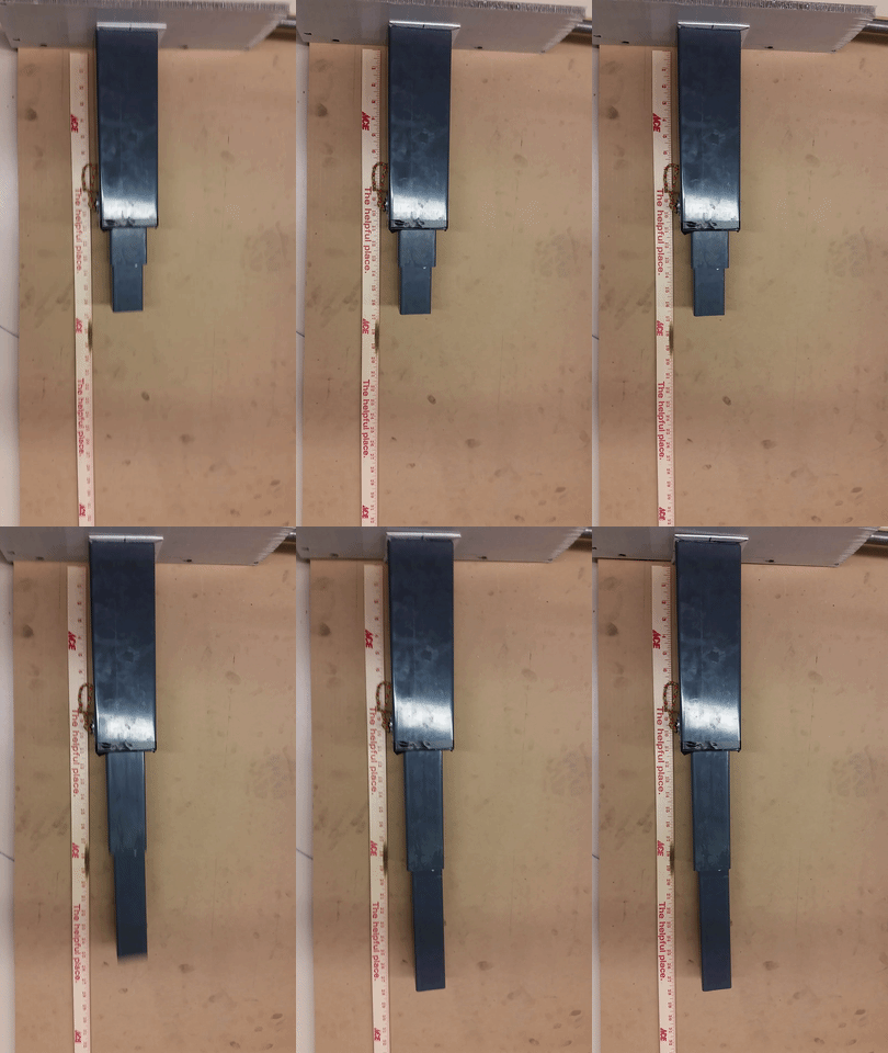
H.F. Hauff is a company based out of Yakima which specializes in farming equipment. One of their products is a trailer which has a wind machine attached to it. In order to keep the fan’s thrust from tipping the trailer over, the trailer needs outriggers to extend out. The outriggers also serve as a way to level out the trailer in uneven surfaces. The outriggers are what needed to be designed. This portion of the project was the vertical arm which extends from the horizontal arm, and goes towards the ground to raise the trailer. The project consisted of three stages. The first stage was to design the vertical arm. The design consisted of three segments of square tubing which all fit within each other. The actuation mechanism was to be cable, as opposed to hydraulic in order to reduce cost. The design was made on SolidWorks and drawings were generated. The second stage was the construction of the device. Since the design was a new design, it was constructed out of plastic as a proof of concept. The third stage was to test the device. Becausee the device was constructed simply as a proof that the design would function, it would not support a load. What could be tested was the actual extension and compacting sizes. This would demonstrate whether the arm could level out the trailer in the required grade of slope.


H.F. Hauff Outrigger Project: Vertical Arm
The outrigger was conceived and designed at Central Washington University. H.F. Hauff was involved in the conceptualization and the design requirements. The parts will be made at CWU as well as at H.F. Hauff’s metal working shop. The materials will be provided and funded by H.F. Hauff.
The device functions as a three-piece leg which extends in a cable and pulley assembly. The legs are made of steel square tubing and are cut to the sizes specified in appendix figures B-4 through B6. These legs have internal pieces which are composed of two pulleys, a cylinder and rod, and a cable running through them. The leg is attached to a base plate with two nut and bolt fasteners.
The base plate is made to hold the cylinder and rod, and the leg. This plate has mounting that will attach to the horizontal outrigger with hardware. The baseplate is necessary in order to assemble and disassemble the vertical arm for maintenance.


